Here I will briefly explain the functioning of the different elements that form the experience, and which are their working values.
STEP 1: Optical layout
This is the schema of the optical part.
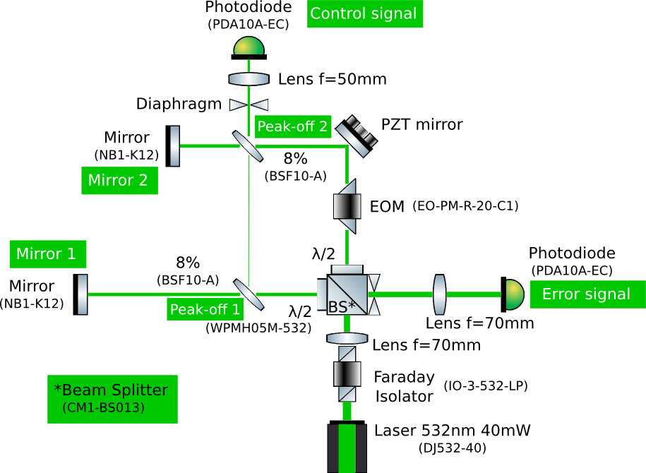
Notice that all elements are fixed to a cage except the peak-off 2. So in case of misalignment and loss of the interference pattern the optics to tune are: for the control signal the peak-off 2 and for the error signal the mirror 1. The laser should work around 300-307 mA. Over 310mA its power starts to oscillate. The working region in terms of temperature goes from 20° to 25°. However experimentally we have checked that it delivers more power at low temperature.
In practice, there are two independent controllers: current and temperature. They both have an on/off button and a second button (LASER/TEC ON). Meanwhile this second button is not on, the controllers will not send any information to the laser. First we have to fix the temperature (Tset) and push TEC ON. Notice that it is driven by a PID and so it takes some time to achieve the desired value. Tact will show the actual temperature. ATTENTION: we can not see both Tset and Tact at the same time so if we touch the button we might change Tset without noticing. Once this is done we can turn on the current controller and increase the current until its nominal value. ATTENTION: put back to zero the current before turning off the device. Otherwise when we turn it on again it will remember the value and it will pass directly from 0 to 300mA.
So to sum up the working point is: 300mA, 20.2°.
STEP 2: Modulation and Demodulation lines
This is the schema of the modulation/demodulation lines.
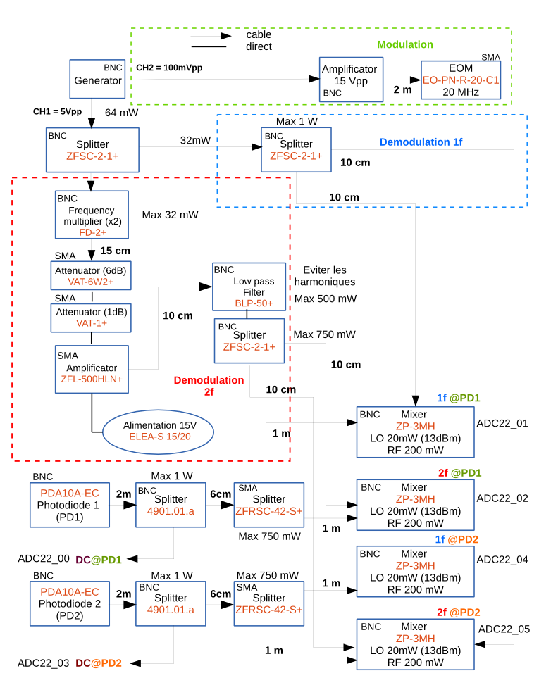
The modulation line is the one that drives the EOM. As it is shown in the upper part of the schema, we use the channel 2 of the generator of functions for this purpose. There is an amplificator between the generator and the EOM which allows us to deliver up to 15Vpp. Notice that the maximum value accepted is 1Vpp and it works in 50Ω. We have chosen the working value (amplitude, frequency) as the one that maximizes the error signal (1f) without decreasing too much its DC.
So channel 2 parameters are: 100mVpp, 20MHz.
The demodulation line has two branches, 1f and 2f. In order to achieve an optimal working of the mixer we need to deliver around 13dB, so we fixed the amplitude of channel 1 according to it.
So channel 1 parameters are: 5Vpp, 20MHz.
STEP 3: Actuator
The actuator in our case is a PZT mirror which is driven by a controller. The signal sent is the sum of the noise we want to kill and the corresponding correction. The schema of the actuation is the following:
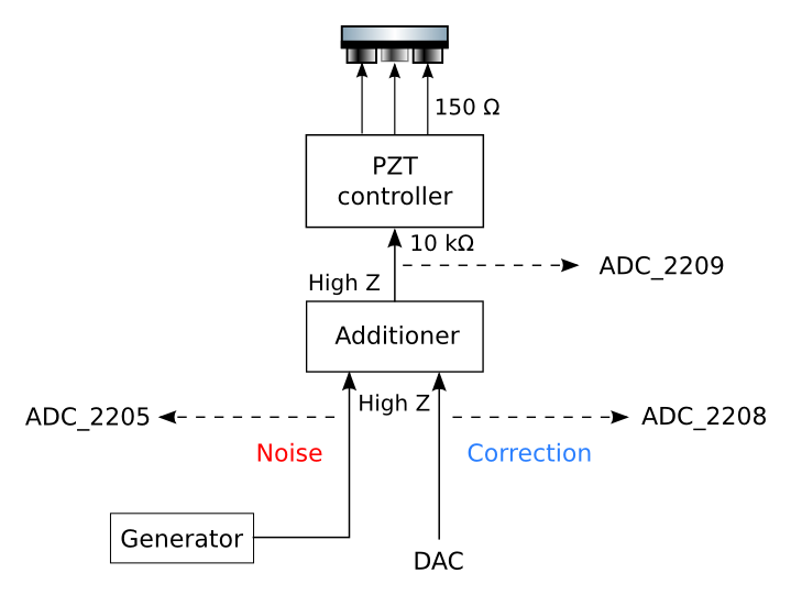
The PZT controller has several limitations. The first one is that it does not accept negative values, so the noise injected has to be always positive as well as the sum noise + correction. In practice this means to add an offset to the noise we inject. We can check it permanently via ADC_2209. Another limitation is the output impedance of 150 Ω because the impedance of the PZT has to be bigger to avoid loading the controller. The PZT behaves as a capacitor so its impedance depends on the frequency of the signal delivered and this limits its bandwidth. In our case the limit is 1.2 kHz, so above it we can not guarantee that the signal delivered is the same that we inject.
Finally the last constraint is the fact that the highest current that the controller is able to deliver is 60 mA which translates into a limit in the voltage as well. For the case of injecting a sine the maximum input amplitude is given by:
Vpp = Imax / (2 * π * Ctot * f * 7.5)
For 1.2 kHz the maximum amplitude that we can inject is 1.2 Vpp. For smaller frequencies we can inject higher amplitudes, but 1 Vpp is more than enough for our purposes so better try to stay around this value.
The additioner is the one in charge of combining the noise and the correction. We monitor both signals via ADC_2205 and ADC_2208. Notice that as we work in High Z, the generator will deliver the double of what it displays (it is 50 Ω adapted). The additioner accepts amplitudes as high as its alimentation (12V max), and its bandwidth goes up to 30kHz. It does not work properly if one of the two inputs is not connected so in case we just need one, we have to connect a 50 Ω charge.
We have checked that the amplitude that provokes a displacement of π (peak-peak) is 400mVpp (200mVpp at the generator).
STEP 4: Phase locking of the generators
In order to ease the control loop, we synchronized the internal clock of both generators so all the signals (noise, modulation, demodulation) have the same time reference. To lock in phase both generators we have to choose first which one will be the reference, in our case the one that produces the noise (Tektronix). After we have to send the reference via a BNC cable to the other generator (Ext Ref Output -> 10MHz In/Out).
Once this is done, we have to change the clock source to external. In order to do so, in the generator Rigol we have to press the button Utility -> System -> Clock Source until it changes to External. If everything works, a message is shown that the generator has been successfully synchronized. At this point both generators share the clock. Now in order to make both signals (modulation and demodulation) in phase, we just have to push Align Phase. At this point the demodulation and the modulation signal are in phase and they have a constant phase difference with respect to the noise produced by the reference generator.
Finally we have to find the phase that maximizes the error signal (1f), the signal that we are interested in using, by adding phase to the modulation signal.
STEP 5: Lock
The process that takes charge of the control loop is FreqStab. I am going to describe the three parts:
- Sensing: we have to put a 1 in gain Green error sig.
- Filtering: there are two possibilities. The one by default is Las_Calva, and it is there where the filter is implemented (pole @ 0.1Hz, gain 1 @ 1Hz). So we have to select it and open the corresponding window. We can choose the gain that we want for our filter in gainPower 1064. The sign is not always the same so it is necessary to try both.
- Driving: finally we need to put gain green to 1 in order to allow anything to be sent. We also have a variable called delay green (sec), which allow us to slightly delay the output in order to optimally cancel the noise. The maximum value is 1s but it is better to keep it as low as possible. Otherwise the system is not able to follow and we might have some problems.
There are several interesting channels to observe when trying to lock: Pr_Green_ACp, Pr_Green_DC, Pr_Green_Control_ACp, Pr_Green_Control_DC (which are the error signal demodulated at 1f, the DC of the error signal, the control signal demodulated at 1f and the DC of the control signal respectively), ADC_2205 and ADC_2208 (noise injected and correction sent). Although the more important is ADC_2209 which show us the sum correction + noise and it is the one that tells us if we are locked or not.